Transmission Line Modeling (TLM) Based Co-Simulation
This chapter gives a short description how to get started using the TLM-Based co-simulation in OMEdit. We introduce a graphical MetaModel editor which is an extension and specialization of the OpenModelica connection editor OMEdit.
In the context of this work a MetaModel is composed of several sub-models including the interconnections between these sub-models. The standard way to store a MetaModel for a TLM based co-simulation is in XML format. The XML schema standard is accessible from tlmModelDescription.xsd
The full graphical functionality of the MetaModel editor for TLM Based co-simulation provides the following general functionalities:
- Import and add External non-Modelica models such as Matlab/SimuLink, Adams, and BEAST models
- External Modelica models such as Dymola and Wolfram SystemModeler models
- Specify startup methods and interfaces of the external model
- Build the MetaModels by connecting the external models
- Set the co-simulation parameters in the MetaModel
- Simulate the MetaModels using TLM based co-simulation
Co-Simulating an Existing MetaModel
This section demonstrates how to load an existing double pendulum MetaModel,co-simulate it, and look at the results using OMEdit.
Loading a MetaModel for Co-Simulation
We will use the Double pendulum MetaModel which is a multibody system that consists of three sub-models: Two OpenModelica Shaft sub-models (Shaft1 and Shaft2) and one SKF/BEAST bearing sub-model that together build a double pendulum. The SKF/BEAST bearing sub-model is a simplified model with only three balls to speed up the simulation.**Shaft1** is connected with a spherical joint to the world coordinate system. The end of Shaft1 is connected via a TLM interface to the outer ring of the BEAST bearing model. The inner ring of the bearing model is connected via another TLM interface to Shaft2. Together they build the double pendulum with two shafts, one spherical OpenModelica joint, and one BEAST bearing.
To load the double pendulum MetaModel , select File > Open MetaModel from the menu and select pendulum.xml.
OMEdit starts loading the MetaModel and will be shown in the Libraries Browser. Double-clicking the MetaModel in the Library Browser will display the double pendulum MetaModel as shown below in Figure 15
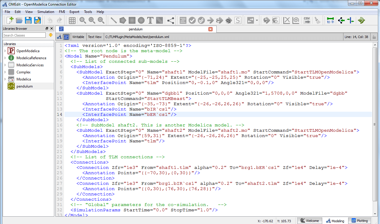
Figure 15 Double Pendulum MetaModel Text View.
Co-Simulating the MetaModel
There are two ways to start co-simulation:
- Click TLM Co-Simulation setup button (
) from the toolbar (requires a MetaModel to be active in MetaModel Widget)
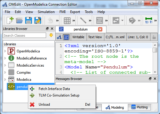
- Right click the MetaModel in the Library Browser and choose TLM Co-Simulation setup from the popup menu (see Figure 16)
The TLM Co-Simulation setup appears as shown below in Figure 17.
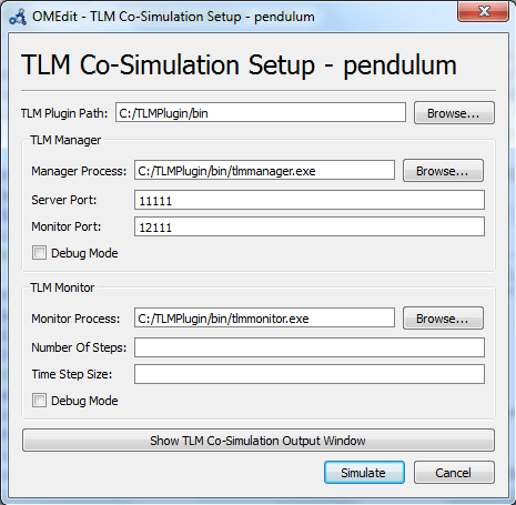
Figure 17 TLM Co-simulation Setup.
Click Simulate from the Co-simulation setup to confirm the co-simulation. Figure 18 will appears in which you will be able to see the progress information of the running co-simulation.
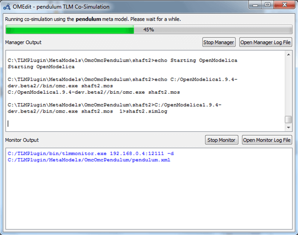
Figure 18 TLM Co-Simulation Progress.
The editor also provides the means of reading the log files generated by the simulation manager and monitor. When the simulation ends, click Open Manager Log File or Open Monitor Log File from the co-simulation progress bar to check the log files.
Plotting the Simulation Results
When the co-simulation of the MetaModel is completed successful, simulation results are collected and visualized in the OMEdit plotting perspective as shown in Figure 19. The Variables Browser display variables that can be plotted. Each variable has a checkbox, checking it will plot the variable.
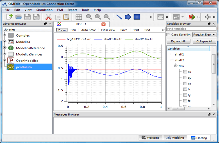
Figure 19 TLM Co-Simulation Results Plotting.
MetaModeling in OMEdit
Preparing External Models
First step in co-simulation Modeling is to prepare the different external simulation models with TLM interfaces. Each external model belongs to a specific simulation tool, such as MATLAB/Simulink*, BEAST, MSC/ADAMS, Dymola and Wolfram SystemModeler.
When the external models have all been prepared, the next step is to load external models in OMEdit by selecting the File > Load External Model(s) from the menu.
OMEdit starts loading the external model and will be shown in the Libraries Browser as shown below in Figure 20
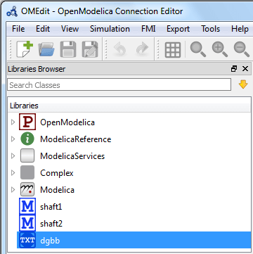
Figure 20 External Models in OMEdit.
Creating a New MetaModel
To create a new MetaModel,select File > New MetaModel from the menu.
Your new MetaModel will appear in the in the Libraries Browser once created. To facilitate the process of textual metamodeling and to provide users with a starting point, the Text View (see Figure 21) includes the MetaModel XML elements and the default simulation parameters.
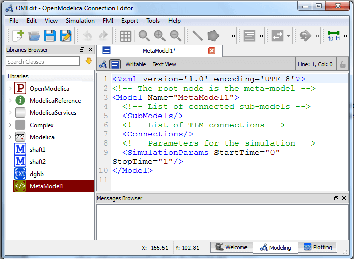
Figure 21 New MetaModel text view.
Saving the MetaModel
Adding Submodels
It is possible to build the double pendulum by drag-and-drop of each simulation model component (sub-model) from the Libraries Browser to the Diagram View. To place a component in the Diagram View of the double pendulum model, drag each external sub-model of the double pendulum(i.e. Shaft1, Shaft2, and BEAST bearing sub-model) from the Libraries Browser to the Diagram View.
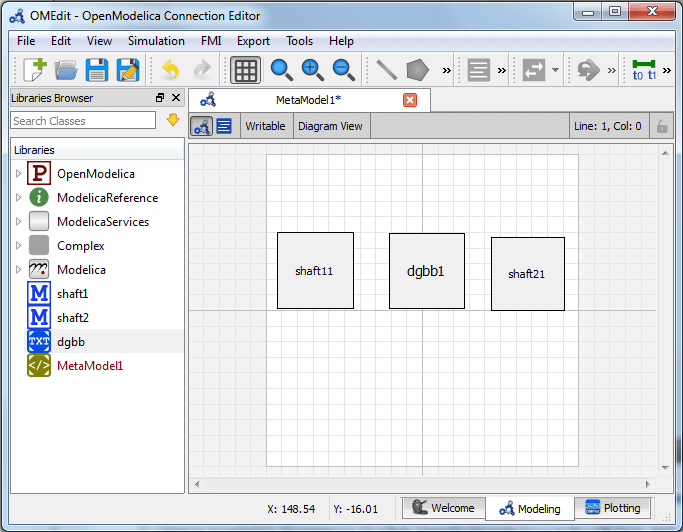
Figure 22 Adding sub-models to the double pendulum MetaModel.
Fetching Submodels Interface Data
To retrieve list of TLM interface data for sub-models, do any of the following methods:
- Click fetch interface points button (
) from the toolbar (requires a MetaModel to be active in ModelWidget)
- Right click the MetaModel in the Library Browser and choose Fetch Interface Data from the popup menu (see Figure 16).
Figure 23 will appears in which you will be able to see the progress information of fetching the interface data.
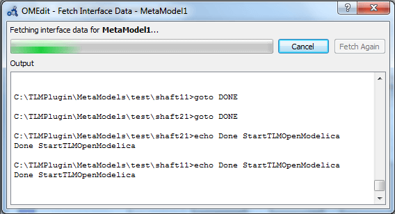
Figure 23 Fetching Interface Data Progress.
Once the TLM interface data of the sub-models are retrieved, the interface points will appear in the diagram view as shown below in Figure 24.
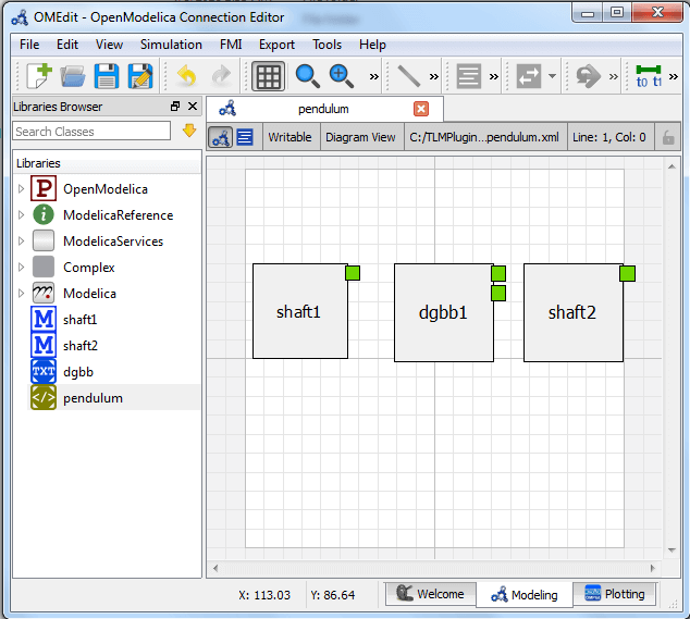
Figure 24 Fetching Interface Data.
Connecting Submodels
When the sub-models and interface points have all been placed in the Diagram View
, similar to Figure 24, the next step is to connect the sub-models.
Sub-models are connected using the Connection Line Button () from the toolbar.
To connect two sub-models, select the Connection Line Button and place the mouse cursor over an interface and click the left mouse button, then drag the cursor to the other sub-model interface, and click the left mouse button again. A connection dialog box as shown below in Figure 25 will appear in which you will be able to specify the connection attributes.
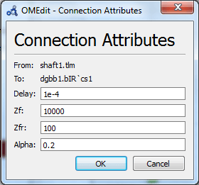
Figure 25 Sub-models Connection Dialog.
Continue to connect all sub-models until the MetaModel Diagram View looks like the one in Figure 26 below.
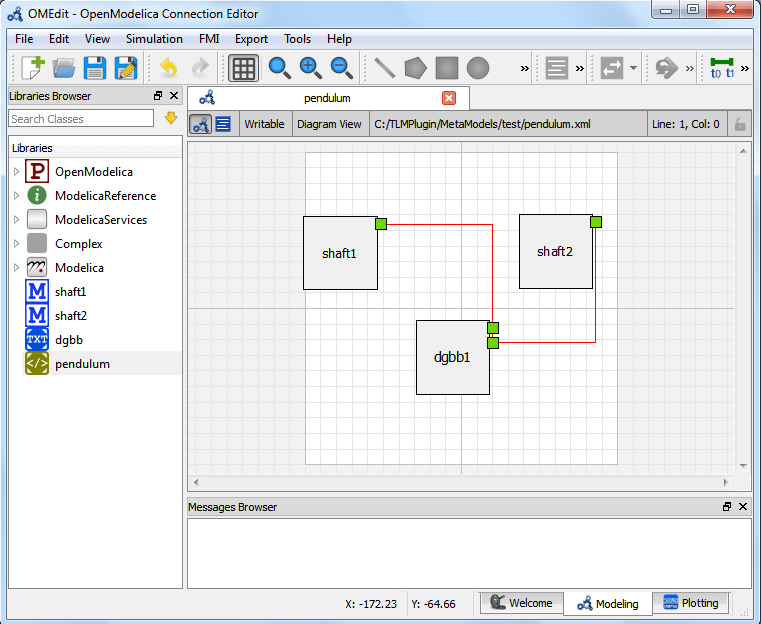
Figure 26 Connecting sub-models of the Double Pendulum MetaModel.
Changing Parameter Values of Submodels
To change a parameter value of a sub-model, do any of the following methods:
- Double-click on the sub-model you want to change its parameter
- Right click on the sub-model and choose Attributes from the popup menu
The parameter dialog of that sub-model appears as shown below in Figure 27 in which you will be able to specify the sub-models attributes.
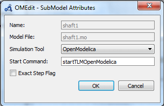
Figure 27 Changing Parameter Values of Sub-models Dialog.
Changing Parameter Values of Connections
To change a parameter value of a connection, do any of the following methods:
- Double-click on the connection you want to change its parameter
- Right click on the connection and choose Attributes from the popup menu.
The parameter dialog of that connection appears (See Figure 25) in which you will be able to specify the connections attributes.
Changing Co-Simulation Parameters
To change the co-simulation parameters, do any of the following methods:
- Click Simulation Parameters button (
) from the toolbar (requires a MetaModel to be active in MetModel Widget)
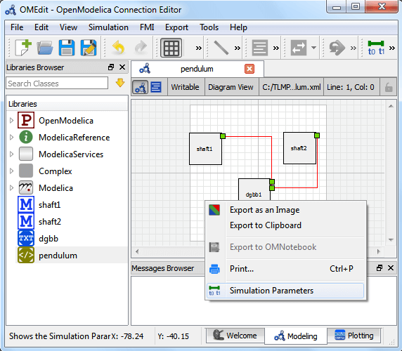
- Right click an empty location in the Diagram View of the MetaModel Widget and choose Simulation Parameters from the popup menu(see Figure 28)
The co-simulation parameter dialog of the MetaModel appears as shown below in Figure 29 in which you will be able to specify the simulation parameters.
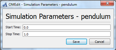
Figure 29 Changing Co-Simulation Parameters Dialog.
