FMI and TLM-Based Simulation and Co-simulation of External Models
Functional Mock-up Interface - FMI
The new standard for model exchange and co-simulation with Functional Mockup Interface (FMI) allows export of pre-compiled models, i.e., C-code or binary code, from a tool for import in another tool, and vice versa. The FMI standard is Modelica independent. Import and export works both between different Modelica tools, or between certain non-Modelica tools.
See also OMSimulator documentation.
FMI Export
To export the FMU use the OpenModelica command translateModelFMU(ModelName) or buildModelFMU(ModelName) <https://build.openmodelica.org/Documentation/OpenModelica.Scripting.buildModelFMU.html>`_ from command line interface, OMShell, OMNotebook or MDT. The export FMU command is also integrated with OMEdit. Select File > Export > FMU the FMU package is generated in the current directory of omc. You can use the cd() command to see the current location. You can set which version of FMI to export through OMEdit settings, see section FMI Options.
To export the bouncing ball example to an FMU, use the following commands:
>>> loadFile(getInstallationDirectoryPath() + "/share/doc/omc/testmodels/BouncingBall.mo")
true
>>> translateModelFMU(BouncingBall)
"«DOCHOME»/BouncingBall.fmu"
>>> system("unzip -l BouncingBall.fmu | egrep -v 'sources|files' | tail -n+3 | grep -o '[A-Za-z._0-9/]*$' > BB.log")
0
After the command execution is complete you will see that a file BouncingBall.fmu has been created. Its contents varies depending on the current platform. On the machine generating this documentation, the contents in Listing 2 are generated (along with the C source code).
binaries/
binaries/linux64/
binaries/linux64/BouncingBall_FMU.libs
binaries/linux64/BouncingBall.so
modelDescription.xml
A log file for FMU creation is also generated named ModelName_FMU.log. If there are some errors while creating FMU they will be shown in the command line window and logged in this log file as well.
By default an FMU that can be used for both Model Exchange and Co-Simulation is generated. We support FMI 1.0 & FMI 2.0 for Model Exchange FMUs and FMI 2.0 for Co-Simulation FMUs.
Currently the Co-Simulation FMU uses the forward Euler solver as default with root finding which does an Euler step of communicationStepSize in fmi2DoStep. Events are checked for before and after the call to fmi2GetDerivatives.
For FMI 2.0 for Co-Simulation OpenModelica can export an experimental implementation of SUNDIALS CVODE (see 1) as internal integrator.
To export a Co-Simulation FMU with CVODE for the bouncing ball example use the following commands:
>>> loadFile(getInstallationDirectoryPath() + "/share/doc/omc/testmodels/BouncingBall.mo")
true
>>> setCommandLineOptions("--fmiFlags=s:cvode")
true
>>> translateModelFMU(BouncingBall, version = "2.0", fmuType="cs")
"«DOCHOME»/BouncingBall.fmu"
>>> system("unzip -cqq BouncingBall.fmu resources/BouncingBall_flags.json > BouncingBall_flags.json")
0
The FMU BouncingBall.fmu will have a new file BouncingBall_flags.json in its resources directory. By manualy changing its contant users can change the solver method without recompiling the FMU.
The BouncingBall_flags.json for this example is displayed in Listing 3.
{
  "s" : "cvode"
}
For this to work OpenModelica will export all needed dependencies into the FMU if and only if the flag fmiFlags was set. To have CVODE in a SourceCode FMU the user needs to add all sources for SUNDIALS manualy and create a build script as well.
CMake FMU Export
A prototype implementation of FMUs compiled with CMake instead of Makefiels is available when using compiler flag --fmuCMakeBuild. This is useful for creating Source-Code FMUs and for cross-platform compilation. On Windows this is currently the only way to use Docker images for cross-platform compilation.
It is possible to add runtime dependencies into the FMU using --fmuRuntimeDepends. The default value modelica will include every external libraries mentioned by an annotation as well as its dependencies (recursive). The system default locations are excluded.
The minimum CMake version required is v3.21.
FMI Import
If you want to simulate a single, stand-alone FMU, or possibly a connection of several FMUs, the recommended tool to do that is OMSimulator, see the OMSimulator documentation for further information.
FMI Import allows to use an FMU, generated according to the FMI for Model Exchange 2.0 standard, as a component in a Modelica model. This can be useful if the FMU describes the behaviour of a component or sub-system in a structured Modelica model, which is not easily turned into a pure FMI-based model that can be handled by OMSimulator.
FMI is a computational description of a dynamic model, while a Modelica model is a declarative description; this means that not all conceivable FMUs can be successfully imported as Modelica models. Also, the current implementation of FMU import in OpenModelica is still somewhat experimental and not guaranteed to work in all cases. However, if the FMU-ME you want to import was exported from a Modelica model and only represents continuous time dynamic behaviour, it should work without problems when imported as a Modelica block.
Please also note that the current implementation of FMI Import in OpenModelica is based on a built-in wrapper that uses a reinit() statement in an algorithm section. This is not allowed by the Modelica Language Specification, so it is necessary to set the compiler to accept this non-standard construct by setting the --allowNonStandardModelica=reinitInAlgorithms compiler flag. In OMEdit, you can set this option by activating the Enable FMU Import checkbox in the Tools | Options | Simulation | Translation Flags tab. This will generate a warning during compilation, as there is no guarantee that the imported model using this feature can be ported to other Modelica tools; if you want to use a model that contains imported FMUs in another Modelica tool, you should rely on the other tool's import feature to generate the Modelica blocks corresponding to the FMUs.
After setting the --allowNonStandardModelica flag, to import the FMU package use the OpenModelica command importFMU,
>>> list(OpenModelica.Scripting.importFMU, interfaceOnly=true)
function importFMU
  input String filename "the fmu file name";
  input String workdir = "<default>" "The output directory for imported FMU files. <default> will put the files to current working directory.";
  input Integer loglevel = 3 "loglevel_nothing=0;loglevel_fatal=1;loglevel_error=2;loglevel_warning=3;loglevel_info=4;loglevel_verbose=5;loglevel_debug=6";
  input Boolean fullPath = false "When true the full output path is returned otherwise only the file name.";
  input Boolean debugLogging = false "When true the FMU's debug output is printed.";
  input Boolean generateInputConnectors = true "When true creates the input connector pins.";
  input Boolean generateOutputConnectors = true "When true creates the output connector pins.";
  input TypeName modelName = $Code(Default) "Name of the generated model. If default then the name is auto generated using FMU information.";
  output String generatedFileName "Returns the full path of the generated file.";
end importFMU;
The command could be used from command line interface, OMShell, OMNotebook or MDT. The importFMU command is also integrated with OMEdit through the File > Import > FMU dialog: the FMU package is extracted in the directory specified by workdir, or in the current directory of omc if not specified, see Tools > Open Working Directory.
The imported FMU is then loaded in the Libraries Browser and can be used as any other regular Modelica block.
Transmission Line Modeling (TLM) Based Co-Simulation
This chapter gives a short description how to get started using the TLM-Based co-simulation accessible via OMEdit.
The TLM Based co-simulation provides the following general functionalities:
Import and add External non-Modelica models such as Matlab/SimuLink, Adams, and BEAST models
Import and add External Modelica models e.g. from tools such as Dymola or Wolfram SystemModeler, etc.
Specify startup methods and interfaces of the external model
Build the composite models by connecting the external models
Set the co-simulation parameters in the composite model
Simulate the composite models using TLM based co-simulation
Composite Model Editing of External Models
The graphical composite model editor is an extension and specialization of the OpenModelica connection editor OMEdit. A composite model is composed of several external sub-models including the interconnections between these sub-models. External models are models which need not be in Modelica, they can be FMUs, or models accessed by proxies for co-simulation and connected by TLM-connections. The standard way to store a composite model is in an XML format. The XML schema standard is accessible from tlmModelDescription.xsd. Currently composite models can only be used for TLM based co-simulation of external models.
Loading a Composite Model for Co-Simulation
To load the composite model, select File > Open Composite Model(s) from the menu and select compositemodel.xml.
OMEdit loads the composite model and show it in the Libraries Browser. Double-clicking the composite model in the Libraries Browser will display the composite model as shown below in Figure 45.
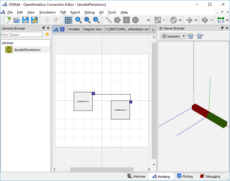
Figure 45 Composite Model with 3D View.
Co-Simulating the Composite Model
There are two ways to start co-simulation:
Click TLM Co-Simulation setup button (
) from the toolbar (requires a composite model to be active in ModelWidget)
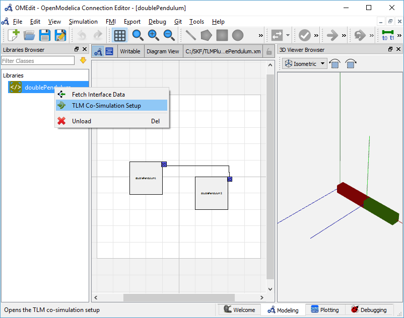
Right click the composite model in the Libraries Browser and choose TLM Co-Simulation setup from the popup menu (see Figure 46)
The TLM Co-Simulation setup appears as shown below in Figure 47.
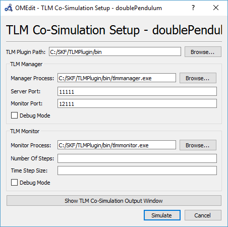
Figure 47 TLM Co-simulation Setup.
Click Simulate from the Co-simulation setup to confirm the co-simulation. Figure 48 will appears in which you will be able to see the progress information of the running co-simulation.
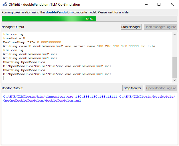
Figure 48 TLM Co-Simulation Progress.
The editor also provides the means of reading the log files generated by the simulation manager and monitor. When the simulation ends, click Open Manager Log File or Open Monitor Log File from the co-simulation progress bar to check the log files.
Plotting the Simulation Results
When the co-simulation of the composite model is completed successful, simulation results are collected and visualized in the OMEdit plotting perspective as shown in Figure 49 and Figure 50. The Variables Browser display variables that can be plotted. Each variable has a checkbox, checking it will plot the variable.
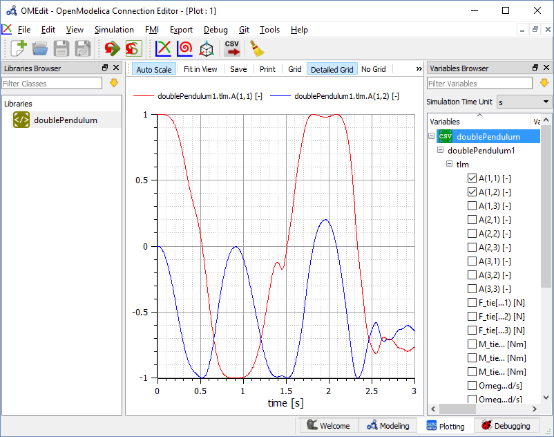
Figure 49 TLM Co-Simulation Results Plotting.
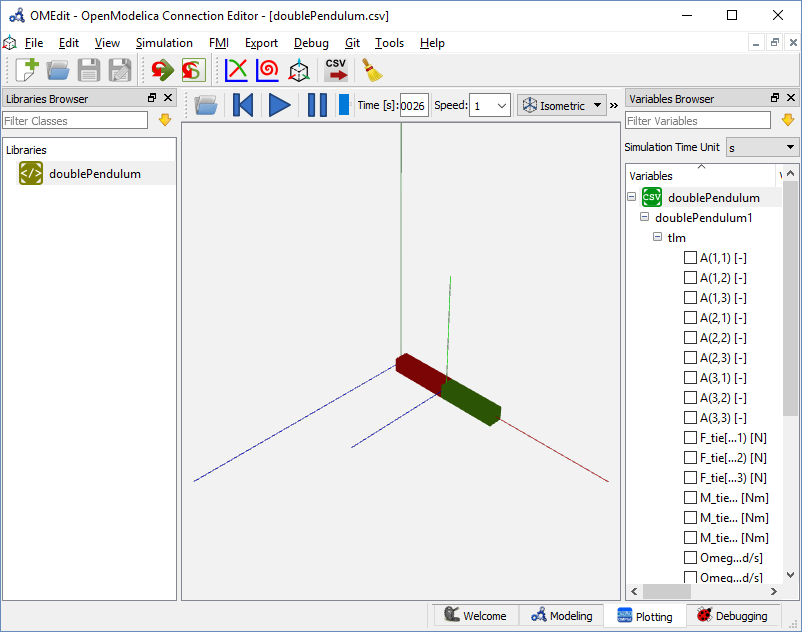
Figure 50 TLM Co-Simulation Visualization.
Preparing External Models
First step in co-simulation Modeling is to prepare the different external simulation models with TLM interfaces. Each external model belongs to a specific simulation tool, such as MATLAB/Simulink*, BEAST, MSC/ADAMS, Dymola and Wolfram SystemModeler.
When the external models have all been prepared, the next step is to load external models in OMEdit by selecting the File > Load External Model(s) from the menu.
OMEdit loads the external model and show it in the Libraries Browser as shown below in Figure 51.
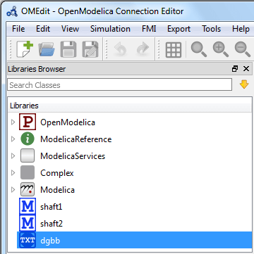
Figure 51 External Models in OMEdit.
Creating a New Composite Model
We will use the "Double pendulum" composite model which is a multibody system that consists of three sub-models: Two OpenModelica Shaft sub-models (Shaft1 and Shaft2) and one SKF/BEAST bearing sub-model that together build a double pendulum. The SKF/BEAST bearing sub-model is a simplified model with only three balls to speed up the simulation. Shaft1 is connected with a spherical joint to the world coordinate system. The end of Shaft1 is connected via a TLM interface to the outer ring of the BEAST bearing model. The inner ring of the bearing model is connected via another TLM interface to Shaft2. Together they build the double pendulum with two shafts, one spherical OpenModelica joint, and one BEAST bearing.
To create a new composite model select File > New Composite Model from the menu.
Your new composite model will appear in the in the Libraries Browser once created. To facilitate the process of textual composite modeling and to provide users with a starting point, the Text View (see Figure 52) includes the composite model XML elements and the default simulation parameters.
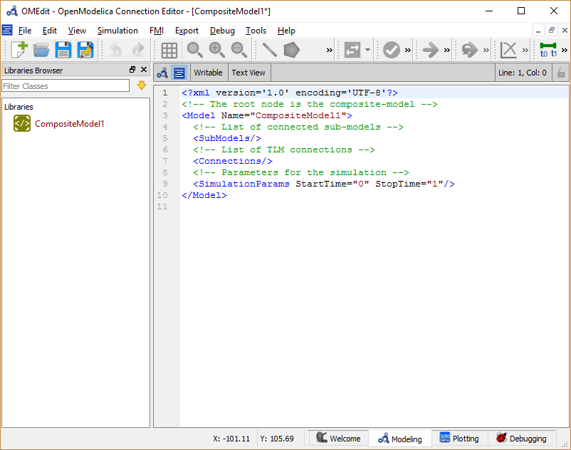
Figure 52 New composite model text view.
Adding Submodels
It is possible to build the double pendulum by drag-and-drop of each simulation model component (sub-model) from the Libraries Browser to the Diagram View. To place a component in the Diagram View of the double pendulum model, drag each external sub-model of the double pendulum (i.e. Shaft1, Shaft2, and BEAST bearing sub-model) from the Libraries Browser to the Diagram View.
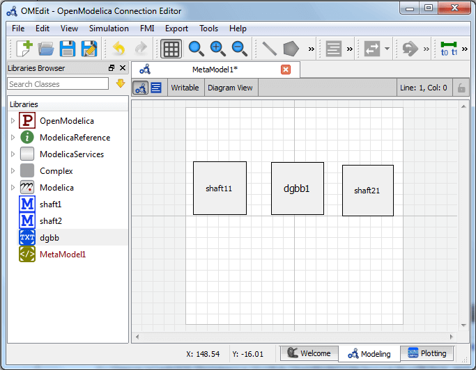
Figure 53 Adding sub-models to the double pendulum composite model.
Fetching Submodels Interface Data
To retrieve list of TLM interface data for sub-models, do any of the following methods:
Click Fetch Interface Data button (
) from the toolbar (requires a composite model to be active in ModelWidget)
Right click the composite model in the Library Browser and choose Fetch Interface Data from the popup menu (see Figure 46).
To retrieve list of TLM interface data for a specific sub-model,
Right click the sub-model inside the composite model and choose Fetch Interface Data from the popup menu.
Figure 54 will appear in which you will be able to see the progress information of fetching the interface data.
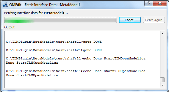
Figure 54 Fetching Interface Data Progress.
Once the TLM interface data of the sub-models are retrieved, the interface points will appear in the diagram view as shown below in Figure 55.
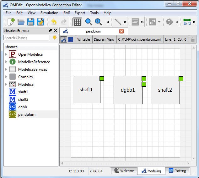
Figure 55 Fetching Interface Data.
Connecting Submodels
When the sub-models and interface points have all been placed in the Diagram
View, similar to Figure 55, the next step is to
connect the sub-models. Sub-models are connected using the Connection Line
Button () from the toolbar.
To connect two sub-models, select the Connection Line Button and place the mouse cursor over an interface and click the left mouse button, then drag the cursor to the other sub-model interface, and click the left mouse button again. A connection dialog box as shown below in Figure 56 will appear in which you will be able to specify the connection attributes.
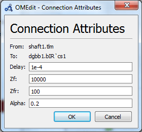
Figure 56 Sub-models Connection Dialog.
Continue to connect all sub-models until the composite model Diagram View looks like the one in Figure 57 below.
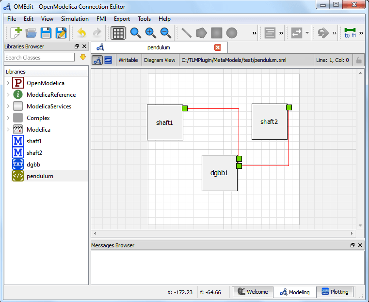
Figure 57 Connecting sub-models of the Double Pendulum Composite Model.
Changing Parameter Values of Submodels
To change a parameter value of a sub-model, do any of the following methods:
Double-click on the sub-model you want to change its parameter
Right click on the sub-model and choose Attributes from the popup menu
The parameter dialog of that sub-model appears as shown below in Figure 58 in which you will be able to specify the sub-models attributes.
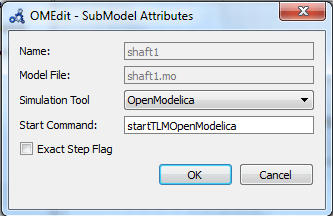
Figure 58 Changing Parameter Values of Sub-models Dialog.
Changing Parameter Values of Connections
To change a parameter value of a connection, do any of the following methods:
Double-click on the connection you want to change its parameter
Right click on the connection and choose Attributes from the popup menu.
The parameter dialog of that connection appears (see Figure 56) in which you will be able to specify the connections attributes.
Changing Co-Simulation Parameters
To change the co-simulation parameters, do any of the following methods:
Click Simulation Parameters button (
) from the toolbar (requires a composite model to be active in ModelWidget)
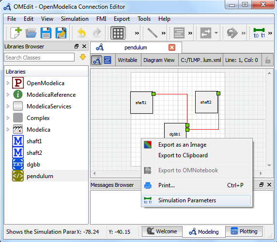
Right click an empty location in the Diagram View of the composite model and choose Simulation Parameters from the popup menu (see Figure 59)
The co-simulation parameter dialog of the composite model appears as shown below in Figure 60 in which you will be able to specify the simulation parameters.
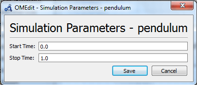
Figure 60 Changing Co-Simulation Parameters Dialog.
Footnotes
